 This idea of mine has been in circulation for some time now and I’ve been handing out the plans and measurements. So here now the polished (not handdrawn on a napkin) documentation on how to build my brake line release toggles.
I tried to solve some issues that bother me with other designs, so the design goals were:
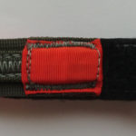
- Make them easily maintainable, therefore enable the next rigger to easily and quickly replace the velcro or other maintenance parts without having to take any other portion of the toggle apart.
- Easy to manufacture, and as little parts as possible.
- No metal or cable parts.
This of course comes at a cost:
- Higher pull force to release than other designs.
- In some spots tight manufacturing tolerances. (highlighted below)
The pdf version and the dxf (Autocad or Librecad) files.
I publish this under GPLv3 (see details at the bottom and full licence text here), in short, you can modify, distribute, use this commercially, as much as you want as long as you publish your modifications openly under the same licence and attribute the original author.
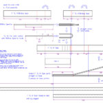
A few notes and things to watch out for when building:
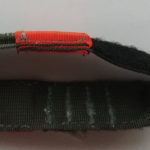
- Build yourself a little folder tool for manufacturing the folded 1″ square weave portions.
- The short and long piece of folded 1″ square weave are to be 301 straight stitched together.
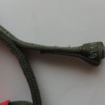
- The nose portion is to be 301 straight stitched with 2(!) passes to give it more stiffness.
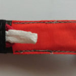
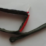
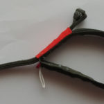
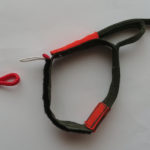
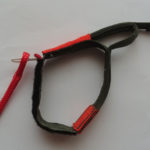
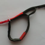
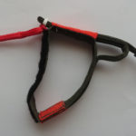
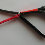
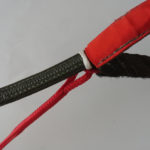
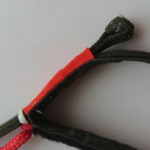
- This has been tested with 1000lbs Spectra for the loop portion. Do not use anything heavier because it can lead to hesitations when releasing since heavier line will not be easily bent back through the red loop on release. Do not use excessively thinner, because it can cut into the toggle nose more and therefore increase the pull force required for releasing. Do not use anything but spectra, it has the lowest friction coefficient of all common line types, everything else will increase pull forces.
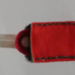
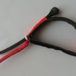
- The distance inbetween the point of where the orange tunnel on the back of the toggle ends, and the point where the folded 1″ square weave material is stitched to the back of the toggle is critical. Too far and the nose can easily be “pushed” from the top, too close and the toggle becomes hard to release or the nose cannot retract enough anymore to release in the first place.
- The lenght of the two loops is critical. The white loop has to be long enough to have some of the load put on the red loop when load is put on the break line. The red loop should be tight, but not too tight for obvious reasons.
- If the tape tunnel for the toggle nose is too tight, releasing the line will require more force. (duh.)
Rigging / Attaching the toggles to the brake line:
Copyright (C) 2016 Thomas Hirsch
This information is free; you can redistribute it and/or modify it
under the terms of the GNU General Public License version 3 as published by
the Free Software Foundation.
This work is distributed in the hope that it will be useful,
but WITHOUT ANY WARRANTY; without even the implied warranty of
MERCHANTABILITY or FITNESS FOR A PARTICULAR PURPOSE. See the
GNU General Public License for more details.
You should have received a copy of the GNU General Public License
along with this work; if not, write to the Free Software
Foundation, Inc., 51 Franklin Street, Fifth Floor, Boston, MA 02110-1301, USA.